|
| |
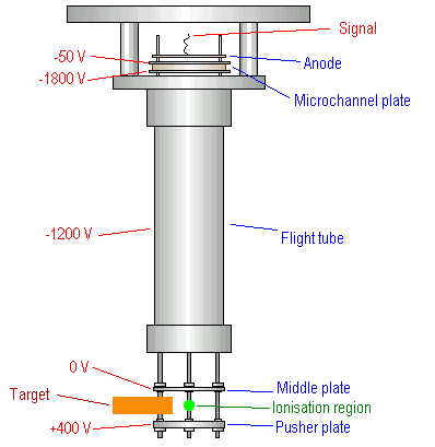
Time-of-Flight Mass Spectrometer and Detection ElectronicsThe simulated dust grain target is mounted at the sampling end of a time-of-flight mass spectrometer (TOF). Any H2 product which desorbs from the target and becomes ionised by the laser will form H2+ ions; a plate held at a positive potential of ~400 V forces these ions to enter the mass spectrometer for detection. The time interval between the laser pulse and the ion detection signal gives the mass of the ion, hence the name of this type of spectrometer. The time interval required for H2+ to traverse the spectrometer is easily calculated (~1 microsecond for our instrument), hence the TOF can be tuned to exclusively monitor these ions.
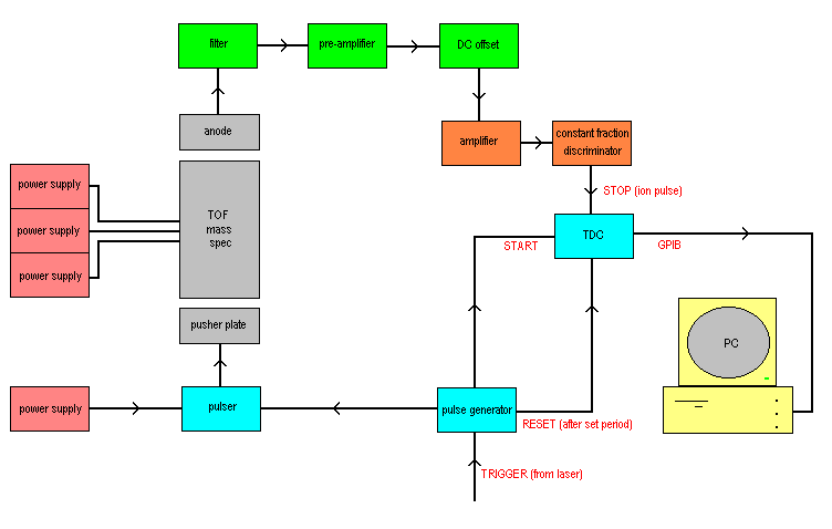
The pusher plate forces the ions through a grid in the middle plate (held at 0 V and positioned above the target), and into the flight tube (held at -1200 V). This large potential difference over the small distance between the target and the flight tube (~4.5 cm) allows most of the H2+ ions to be collected. At the top of the flight tube is a microchannel plate detector. The lower surface of this is held at a potential of -1800 V and the upper side at -50 V. The channel plate consists of a material with a very low work function, such that a cascade of electrons is released from the top whenever an ion strikes the lower surface. The subsequent electron pulse from the top of the channel plate strikes an anode, which passes the signal through some pulse shaping and amplification electronics to the counting electronics where the pulses are recorded. The time of flight of the ions in the spectrometer is measured by comparing the time between a start signal and a stop signal. The start signal is triggered by the laser pulse, which primes a time-to-digital convertor (TDC). The stop signal comes from the electron pulse collected by the anode of the TOF. The TDC can detect up to eight stop signals for a start signal, hence the detection efficiency is increased. The TDC then sends the timing information to a PC, which displays the data as a histogram of number of counts against the time of flight. In an alternative configuration, an electron gun can be used to produce ions rather than the laser. This gives the advantage that any molecule in any internal energy state can be ionised to produce a TOF signal.
This page last modified 26 October, 2007 by John Edridge |


